Experimental: To prepare the C/C composites for the study, the Pan-based carbon fibers chopped to a length of 4.5mm were first impregnated with a resole-type phenolic resin in a plastic mold in vacuum to form a prepreg. The prepreg was pre-cured in an oven at 70°C for 6h to remove excess solvent, followed by a hot-press curing process in a stainless steel mold at 160°C for 30min. The cured composite was machined into doughnut-shaped samples, followed by post-curing in an air-circulated oven to 160°C at a heating rate of 1°C/min and then to 230°C at a heating rate of 0.5°C/min. The samples were held at 230°C for 8h to complete the post-curing process.
Carbonization was conducted by heating the post-cured composite in nitrogen atmosphere to 1200°C at three different heating rates (1, 100 and 1000°C/min). Carbonization at 1°C/min was conducted in an ordinary furnace heated by SiC heating element in nitrogen. The nitrogen gas was introduced continuously into the furnace during

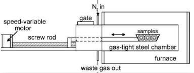
fig.1-schematic-drawing-of-apparatus-for-high-speed-carbonizaton
the entire carbonization process. Carbonization at higher heating rates was conducted using an apparatus specially designed for the study, as schematically shown in fig.1. This apparatus was attached to a furnace enclosing a stainless steel gas-tight chamber with a motor-driven screw rod. When the desired temperature (1200°C) was reached, the sample holder was pushed into the center of the furnace at a controlled, constant speed.
The first-carbonized samples were graphitized to 2200°C at a heating rate of 10°C/min and held for 30min in a helium-purged furnace.The porous graphitized composite was then densified by re-impregnation with same phenolic resin in vacuum, followed by same curing, post-curing and carbonization procedure. To improve the density and properties of the composite, four such densification/carbonization cycles and a second graphitization treatment were applied to all samples. The second-graphitization samples prepared with carbonization rates of 1, 100 and 1000°C/min are designated G1-1, G2-100 and G2-1000, respectively.
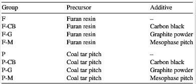
As mentioned earlier, to improve the tribological performance of the fast-carbonized composite, a post-treatment comprising re-impregnation of a carbonaceous additive-doped liquid precursor was applied to G2-1000. To liquid precursors including furan resin and coal tar pitch with three additives including carbon black, graphite powder

table.3-designation-of-samples-prepared-from-different-post-treatments
and mesophase pitch were used. The procedure for impregnating the thermosetting furan resin was the same as for phenolic resin. Impregnating coal tar pitch was carried out in a vacuum chamber at 110°C to allow the pitch to have a viscosity low enough to infiltrate into the open pores of the second-graphitized composite. Designation of samples prepared from different precursors/additives for the final cycle is given in Table 3.
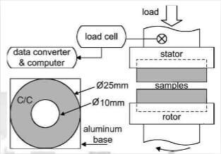
Friction and wear tests of C/C composite were conducted in air with relative humidity of 50-60% using a homemade disk-on-disk sliding wear tester, as schematially shown in fig.2. For the samples having an outer

fig.2-schematic-drawing-of-sliding-wear-tester-sample-specification
diameter of 25mm and inner diameter of 10mm, one unit rmp is equivalent to an average linear speed of 0.055m/min. A load of 0.8 Mpa and fixed rotor speed of 1000 rpm were used for all tests. Prior to testing, all samples were mechanical polished to #1200 grit level, followed by ultrasonic cleaning to remove debris on surface. The constant speed slide testing was performed by first accelerating the rotor sample to the desired speed. When the rotor speed was reached, the stator sample was loaded with a normal pressure of 0.8 Mpa against the rotor for 2min, before the power of the motor was automatically switched off. Prior to each subsequent test, the samples were allowed to cool to room temperature. The tests were conducted for six times for each sample. The COF, μ, was determined using the equation, μ=M/(r×Fn), where M is the torque, Fn the normal force and r the average radius of the sample. The specific were rate coefficient, k (mm3/Nm), was calculated according to the eqation k=V/(F×s), where V is the wear volume, F the normal load and s the sliding distance.
results and discussion