To conduct degradation testing of the bipolar plate materials, specialized fuel cell test “rigs” are required. These rigs must be capable of extended operation without failure, but need not provide the load stability, transient capability, etc., which are of paramount importance in typical small-scale fuel cell tests. Furthermore, it is desirable to provide this functionality at a low cost. To this end, a ganged array of six fuel test stations built to a common design have been constructed. The performance of these test stations will be baselined using graphite monopolar plates. After a baseline has been established, testing of new composite plates will then be initiated.
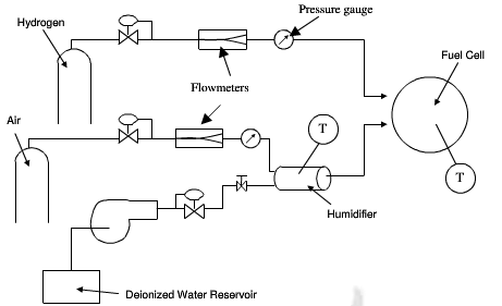
The flow schematic for the test stands is shown in figure 3.7. The stands are currently configured for ambient

fuel cell test stand flow schematic
pressure operation, but can be easily upgraded to 3-bar operation. The stands employ a DTI-designed unipolar cell fixture that is electrically heated to provide control of the fuel cell operating temperature. The anode hydrogen feed is delivered from a plenum, then metered dry through a rotameter and delivered dry and at room temperature to the anode inlet. The cathode air is likewise supplied through a plenum, then metered dry into an electrically heated, packed-bed humidifier. To set the inlet water content, the wxit temperature from this humidifier is controlled. The cathode feed is thus delivered at an elevated temperature and substantially saturated with water vapor to the cell inlet. Because thin, 20um Gore-select polymer electrolyte is used, cathode humidification alone is sufficient to keep the MEA hydrated during the tests.
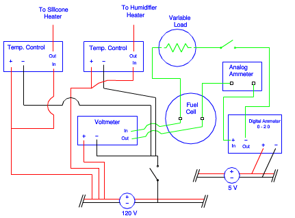
Figure 3.10 shows an electrical schematic of the test system, and illustrates the separate 120VAC, 5VDC, and load

fuel cell test stand electrical schematic
circuits. The test stands are designed such that all necessary readings, controllers and indicators are viewed on the front of the test stand, as shown previously. The main power switch turns on all components that are powered via 120 Volts. The rotameters for the hydrogen and air are clearly scaled and manually controlled with a valve. There are two temperature controllers in each of the test stands. One is used to control the air humidifier temperature and the other is used to control the fuel cell temperature. To determine the fuel cell performance, a voltmeter and two ammeters are wired to the single cell. The digital voltmeter can monitor readings from 0 to 2 Volts. To ensure accurate and consistent readings, the two ammeters are wired in series from the fuel cell. One is a highly accurate digital ammeter that displays 0 to 2.0 A while the other is an analog device displaying 0 to 5.0 A. The analog meter is used as a visual check for current while the digital ammeter is used for acquiring data. Using a separate 5-Volt power source, the digital ammeter is wired individually for each test stand.