The microstructure of one of the lateral surfaces of the test specimens exposed to one cycle and three cycles of thermal shock was analyzed for each peak temperature, followed by the analysis of the top surface of test specimens exposed to one cycle thermal shock condition. Further, test specimens exposed to three cycles of thermal shock were polished in order to analyze the structure within the interior of the C/C composite. All these microstructural analyses together provided reliable predictions of the corresponding modes of oxidation.
Microstructrual examination of test specimens exposed to one cycle thermal shock condition is shown in Fig.4 for

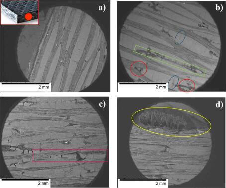
Fig.4-SEM micrograph of 2D CC composite test specimens
different peak temperatures. At 400C, oxidation mechanisms as void growth (shown in red in Fig.4(b)) and transverse crack growth (shown in blue in Fig.4(b)) were observed in the exposed surface, suggesting that oxidizing gas was trying to diffuse through existing cracks/voids located at the lateral surfaces of the test specimens. Likewise, the tow/matrix interface started decomposing at 400C, resembling the initiation of
consumed longitudinal channel that are usually created during an oxidation process. Similar oxidation behavior was observed for test specimens exposed to 600C, however, the tow/matrix interface seemed to be extensively oxidized as macroscopic cracks were developed in the matrix surrounding the tows. This type of material degradation suggests that oxidation attack was concentrated on the exposed surfaces of the test

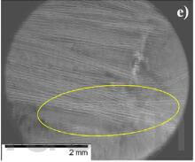
Fig4(e)-SEM micrograph of 2D CC composite test specimens-800C
specimens. Finally, at higher temperatures, i.e., above 600C, both the carbon matrix degradation at the surface and the amount of fibers protruded from the surface increased with increasing thermal shock peak temperature, as shown in yellow in Fig.4(d) and (e) for 700C and 800C test specimens, respectively.
Interface between the longitudinal and transverse fiber tows of pristine specimen and specimens exposed to one
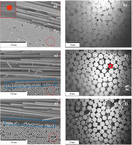
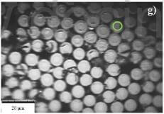
cycle thermal shock condition are shown in Fig.5(a), (c) and (e), whereas Fig.5(b), (d), (f) and (g) show the magnified images of transverse fibers within a two. Fig.5(a) shows the undamaged two/matrix interface and Fig.5(b) demonstrates that the non-oxidized fibers within a two are well packed together by the surrounding carbon matrix. It is observed that the two/matrix interface degradation increased with increasing thermal shock peak temperature, as shown in blue in Fig.5(c) and (e) for 600C and 700C test specimens, respectively. Similar image for the 400C test specimen is not shown as the tow/matrix interface degradation was minimal. Furthermore, as stated earlier, the carbon matrix degraded rapidly with increasing thermal shock peak temperature from 600C to 1000C, leaving gaps between fibers, as shown in Fig.5(d), (f) and (g).

Fig5-SEM micrograph showing tow matrix interface of CC composite

Fig.5(g)-SEM micrograph showing tow matrix interface of CC composite
Therefore, oxidation attack for these test specimens was predominantly found on the exposed surfaces, where the ends of the fibers displayed a pointed morphology as the fiber core is known to be more resistant to oxidation than the fiber edge, as suggested by Han et al., Glime and Cawley and Lamouroux et al. It is important to notice that 1000C test specimen manifested the maximal surface oxidation attack, resulting in the rupture of the denuded ends of the fibers. Consequently, an increase of undamaged fiber core diameter supported this oxidation behavior, which was observed previously by Han et al. in oxidized 3D C/C composites.