Modulus and strength: The mechanical behavior of molded graphite is essentially that of glasses or ceramic materials, i.e., the material is brittle and its strength is a function of the bond strength between crystallites. At ambient temperature, these bonds resist plastic deformation and mechanical failure of molded graphite occurs by brittle fracture. Porosity, flaws, and structural defects concentrate the applied stresses and the material fails at much-lower levels than the theoretical strength of the graphite crystal.

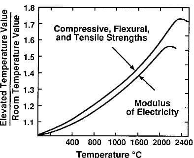
fig.5.6-effect of temperature on strength and modulus of molded graphite
As the temperature is raised, the flaws and structural defects are gradually annealed, stresses are relieved, and plastic deformation becomes possible. The result is a general increase in strength and modulus with increasing temperature. At 2500C, the strength is almost twice the room-temperature strength. Above 2500C, plastic deformation increases and strength decreases. Elongation, which is negligible at ambient temperature, becomes appreciable then and reaches 20% at 2800C. The effect of temperature on strength and modulus is shown in fig.5.6.
Since molded graphite does not deform plastically, at least at low temperatures, measurement of its tensile strength is difficult and unreliable. Instead, it is preferable to measure flexural strength, which is a more reproducible property. Tensile strength is generally 50 to 60% of the flexural strength and compressive strength is approximately twice as much.

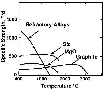
fig.5.7-specific strength as a function of temperature of graphite and other high-temperature materials
Molded graphite has lower strength than metals and most ceramics at ambient temperature. However, at high temperatures this is no longer the case and, above 2000C, molded graphite (and other graphite products) is a superior structural material. This is shown in Fig.5.7, where the specific strength of graphite and other high-temperature materials are shown. Since molded graphite has low density compared to these materials, its specific strength is relatively high.
The room-temperature transverse (flexural) strength of molded-graphite grades varies between 10 and 100Mpa and its Young’s modulus is between 5 and 10 Gpa. These large variations are due to differences in raw materials and processing techniques. Flexural testing is described in detail in the test procedures listed in Table 5.3. In the more common three-point loading test, typical test specimens have a square cross section, 5.08 mm or 3.18 mm on the side. The support span is 3.05mm or 1.52mm for the larger and smaller test specimens, respectively. The strength is given by the following formula:
S=3PL/2bd2
Where S=flexural strength
P=load at rupture
L=support span
b=specimen width
d=specimen thickness