Recently, two alternative techniques of creating flow field structures were suggested: application of particulate etchants and layered deposition. In the particulate etching process the bipolar plate is subjected to a abrasive medium of greater hardness than the plate itself, e.g., by sandblasting, grit blasting, or waterjet cutting. During the particulate etching process the plate surface is covered with an etchant-resistant mask patterned with the desired flow field structure. The second process is completely different from the conventional shaping techniques since it is not based on material removal like etching or machining, but rather on material deposition onto a substrate layer. The substrate layer is comprised of a conductive and impermeable material such as graphite/polymer composite. The three-dimensional structure of the flow field is built up by multiple steps of material deposition through a stencil containing the desired pattern. The deposited material may comprise a highly viscous suspension of conductive particles like carbon in a solvent that evaporates after deposition. Alternatively the conductive particles can be dispersed in a binder that solidifies after deposition in a curing or setting process, e.g., a polymeric binder.
With further commercialization of fuel cells, automated high-volume techniques with low cycle times will be needed for the production of components. To this end, within the last few years many R&D efforts have been undertaken to adopt the injection-molding technique for the processing of graphite/polymer composites. This task is not trivial because the high filling degree of the graphite/polymer composites results in a high viscosity and high flow resistance of the mass. To facilitate injection molding of such composites, polymers of especially low viscosity such as liquid crystal polymers are combined with graphite particles of small size, small specific surface and low aspect ratio. Other helpful measures comprise intensified mixing of the components, mechanical attrition of the polymer particles under liquid nitrogen cooling, and the addition of rheological modifiers to prevent phase separation. Furthermore, injection pressure, injection velocity and nozzle temperature must all be increased as compared to injection molding of conventional plastics.
Independent of the molding technique applied, the higher tendency of the polymer component to flow ultimately leads to accumulation of the polymer in a thin layer at the surface. The increased polymer concentration near the surface was verified by X-ray photoelectron spectroscopy studies.
Electron transfer in the composites occurs along conductive chains formed by the graphite particles. Therefore, the dependence of the conductivity on the graphite concentration is characterized by a percolation threshold. The percolation threshold corresponds to the concentration that is required to build up continuous chains of graphite particles across the plate thickness, and it is very sensitive to changes in the specifications of the starting materials and of the processing technique.
It is obvious that a fine disperse highly porous carbon black percolates at much lower filling degree than the more compact graphite particles. But due to the high surface area of carbon black those compounds are highly viscous, and higher filling degrees are not processable. Combination of graphite powder with a minor weight fraction of carbon black introduces a synergy effect, resulting in a significantly lower resistivity than with a single graphite filler at the same filling degree. The conductive network built up by the binary filler system is assumed to consist of highly dispersed carbon black particles bridged by graphite particles.
For fuel cell application, through-plane conductivities of at least 500 S/cm are necessary. Such high through-plane conductivity is facilitated by the rather random instead of planar orientation of the graphite particles. This random orientation is obvious from polarization microscopy images of the plate cross-section.
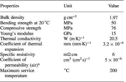
To further illustrate the features and performance of graphite/polymer composite bipolar plates, specifications of plates are compiled in Table 2 bellow.

specifications of graphite polymer composite bipolar plates