Thermal conduction in Brazed Joints: For heat rejection applications, the thermal resistance of the joined assembly relative to the resistance offered by the individual constituents is important. For one-dimensional steady-state heat conduction, the joined materials form a series thermal circuit with an effective thermal resistance, Reff, given from Reff=∑(△xi/Ki), where △xi and Ki represent the thickness and the thermal conductivity, respectively, of the ith layer. For the joints created in this work, △Xc-c=△xCu-Mo=0.25*10-2m, △xbraze ~100*10-6m, KTicusil=219 W/m-K, and KCusil-ABA=180 W/m-K. The value of the thermal conductivity of Cu-clad-Mo, KCu-Mo, varies with the clad layer thickness, and is taken from ref4; KCu-Mo varies from 138W/m-K to 235 W/m-K for 0 to 30% clad layer thickness. For C-C composites, KC-C is anisotropic and varies considerably; for example, for 2D and 3D composites, KC-C=60 and 190 W/m-K perpendicular and parallel to the carbon cloth at 500K, and for 1D composites, KC-C=300 W/m-K at 500K. Taking the average KC-C to be 125 W/m-K for 2D and 3D composites, the effective thermal resistance of our joint assemblies can be computed for a range of clad layer thicknesses. The results shown in figure.8 indicate that Reff varies in the range 31.5 to 38.5*10-6 M2.K/W, and that there is insignificant difference between Ticusil and Cusil-ABA. Because the difference in selecting brazes to satisfy other criteria such as ductility and wetting characteristics without impairing the thermal conductivity and weight advantages of the joined materials.
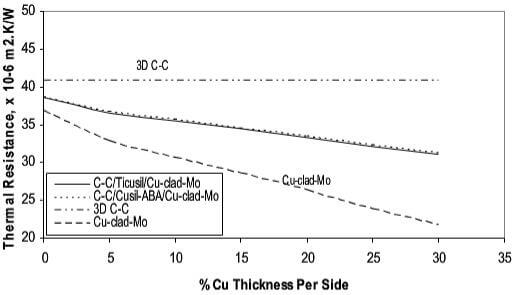
Fig.8-calculated (a) strain energy and (b) effective thermal resistance in the C-C, Cu-clad-Mo joint
Figure.8 also compares the Reff values of the joints to the Reff values of C-C and Cu-clad-Mo substrates of the same total thickness as the joined materials; the thermal resistance of the C-C block is about 40.8*10-6 m2.K/W and that of a Cu-clad-Mo substrate is 22.8*10-6 m2.K/W. The decrease in the thermal conductivity of our joints relative to an isolated Cu-clad-Mo substrate is compensated by a 39% decrease in the weight of the assembly. The Rule-of-Mixtures density of our joints is ~5,919 kg/m3 compared to a density of 9,937 kg/m3 for Cu-clad-Mo alone.
SImilar calculations for the thermal resistance of the joints can be made for 1D C-C composite joined to Cu-clad-Mo. For 1D C-C composites, the effective thermal resistance of the assembly wil be 19.9*10-6 m2.K/W, and for a C-C substrate of the same total thicknesss as the joined assembly, the thermal resistance will be 17.0*10-6 m2.K/W, which is only about 18% less than the effective resistance of the assembly. These simplified thermal considerations illustrate the potential benefits of joining C-C to Cu-clad-Mo to create light-weight heat rejection systems.
Carbon-carbon composites with either pitch+CVI matrix or resi-derived matrix were joined to copper-clad molybdenum using two Ti-containing acive braze alloys. Large-scale braze penetration of the inter-fiber spaces in the CVI C-C composites was observed. The SEM and EDS examination of brazed joints revealed good interfacial bonding in all C-C/Cu-clad-Mo joints, some diffusion and redistribution of alloying elements, and preferential segregation of Ti at the composite/braze interface. The distribution of microhardness across the joints was reproducible, consistent with the Ti content in the braze, and indicated sharp gradients at the Cu-clad-Mo/braze interface. The metallurgically sound composite joints produced in this work, and the projected benefits of reduced thermal stress and thermal resistance, suggest that C-C composite/Cu-clad-Mo joints may be attractive for potential applications in thermal management systems.