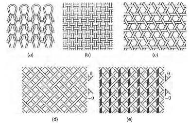
This section covers PAN, pitch and cellulose based carbon fibers, but does not include vapor grown carbon fibers, although such fibers can be spun into stable yarns and converted to chopped fiber. A classification designating the various levels of carbon fiber architecture is outlined in figure 21.1.

classification of carbon fiber architecture
Andersson defines a fabric as an integrated fibrous structure produced by fiber entanglement, or yarn interlacing, interloping, intertwining, or multi-axial placement.
3D textile preforms are particularly important for shaping a reinforcement prior to inclusion in, say, RTM and carbon-carbon composites.
Since carbon fiber is electrically conductive, it is good practice for processors working with carbon fiber, to have designated work areas set aside, so that all electrics can be adequately protected from carbon fiber fly and an efficient air filtration system built into the workplace to safeguard operatives. Oxidized PAN fiber is not electrically conductive, however, and does not have these problems.
With carbon reinforcements, it is possible to incorporate two or more different yarns, to form a hybrid carbon reinforcement, enabling a designer to incorporate properties into a composite that fall between the performance levels of the chosen fibers. So the introduction of an aramid fiber into a carbon fabric reinforcement would improve the impact resistance, albeit at the expense of other mechanical properties. Special scissors are available to cut aramid fibers.
Virgin carbon fiber
A tow of carbon fibers is a plurality of non-twisted continuous carbon filaments, about 5-10 um in diameter, with typical tow sizes of 3k, 6k and 12k, normally surface treated and sized. Larger and less expensive carbon fiber tows, such as 24k, 40k, 48k, 80k, 160k, 320k, 400k and 410k are now becoming more widely available.
Non-woven discontinuous reinforcement (staple fiber)
Adhesive bonded reinforcements
- Chopped strand mat (csm)
A carbon fiber csm consists of a random array of chopped fibers held together by a thermoset or thermoplastic binder. A carbon fiber csm is compatible with polyester and epoxy resin systems and can be incorporated into carbon preforms and held in position by sewing. Composites made from a csm will have low volume fractions, of about 20-25% v/v.
- Carbon fiber tissue
An knife can be used to spread a carbon fiber tow and form a thin veil of carbon fiber or tissue, which can be used to hold a resin rich gel coat on the surface of a fiberglass laminate construction to five a high surface finish concurrent with added microcrack suppression, as well as provide additional chemical resistance. It will give better performance than a glass tissue due to the absence of wicking.
- Carbon fiber paper reinforcement
A paper based on carbon fiber can be made using conventional paper making plant, where chopped fiber is dispersed in a liquid carrier containing wetting and binding agents.
Needled mat
A carbon fiber needled mat is dry laid, having no binder, with the chopped fibers being held together by entanglement. The entanglement is done by using a machine that passes a fiber web under a reciprocating beam holding a large number of barbed needles, which penetrate the fiber web and entangle the fibers as the hooks are withdrawn.
Milled fiber
Initially, an end use was sought for short lengths of carbon fiber, but has now developed into a defined end product. Fiber is sized, cut into a short staple form and milled to give a carbon fiber powder, which is sieved and has become important for incorporating in resin matrices, to confer EMI/RFI shielding, and in automobile air bags, to provide an electrical path for rapid ignition of the explosive charge.
Milled carbon fibers are typically 30-3000 um long, averaging about 300 um with a mean L/D ratio of 30
Chopped carbon fiber
Chopped carbon fiber is generally cut 3 or 6 mm long and sized with glycerol for incorporating in processes using water carrier or a thermoplastic size such polyurethane for integrating with thermoplastic matrices.
Unidirectional fabrics
Definitions to vary, but a unidirectional fabric is normally taken as a fabric with at least 90% of the fiber weight in one direction, which can be in either the warp or the weft direction.
Non-woven UD fabrics
A non-woven carbon fabric is made from fibers held in position by a binder, which can include melt bonding powders and meltable fibers, thermosetting resins and thermoplastic polymers.
Woven UD fabrics including Warp UD fabric and Weft UD fabric.
Woven fabrics (2D planar or biaxial reinforcement)
Warp knitting
Forms of braiding:
There are four main forms of braiding: flat braids; sleevings; wide braided fabric; overbraids
Braid architecture:
There are two main forms of braid architecture:
Blaxial 2D braid and Triaxial 3D braid.
Woven 3D fabrics:
A problem encountered with composites prepared from 2D fabrics is that cleavage can subsequently occur between layers, leading to premature failure of the composite. This is a problem that does not occur with 3D structures due to the lack of laminate.
Proprietary 3D weaving processes
Knitted 3D fabrics
Braided 3D multiaxial
n-D orthogonal blocks: including 3D, 4D 5D blocks.